|
RST Audio Panel Assembly
|
|
Page 2
|
| |
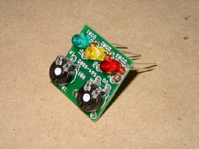
The Diode board
comes next. Don't solder the diodes just yet, as they have to be positioned
to the correct height in the chassis first. Just assemble and solder the
resisters and pots for now.
|
|
|
|
|
|
|
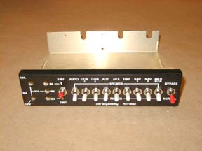
The
Start of the chassis assembly comes next.
Put the three LED lenses in the chassis first. Pushing the in from the
front with the open end to the inside. Red goes on top, with the yellow
in the middle and green on the bottom. Solder the hookup wires to the
display board. Insert the LEDs in to the lenses noting polarity. Slide
the display board onto the leads of the LEDs. Take a screw, spacer, lock
washer, hex nut, and mount the board to the chassis.
Now you can solder the LED leads.
|
|
|
|
|
|
Take all the
switch's hardware off except the last hex nut. Leave about 3 or 4 threads
between the switch body and the hex nut. The lock washer comes next. Followed
by the anti rotation washer. All of these washers need to be modified.
Both sides need to be filed, ground, or cut so that they can fit side
by side.
|
|
|
|
|
|
|
| |
|
|
|
|
|

