|
RST Audio Panel Assembly
|
|
Page 3
|
| |
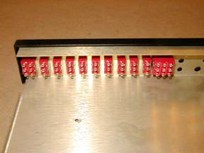
The tooth needs
to face forward on the switch shaft. Insert the first switch into the
chassis. Rotate the switch so the tooth fits into the small hole in the
chassis front. Line up the Black faceplate and push onto the switch's
shaft. Screw on the final hex nut. Follow the same procedure with the
rest of the switches. Note that S-1 and S-11 have more terminals than
the rest of the switches. Consult the manual for placement.
|
|
|
|
|
|
|
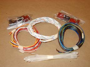
Now comes the real fun part.
There are about a gazillion hook up wires to run. Take the three PC board
mount screws, Stand offs and hex nuts. Insert the screws up from the bottom
of the chassis.
Place a stand off on the screw then a hex nut and tighten.
Place the PC board onto the screws. This will allow you to remove the
board to solder the hook up wires.
|
|
|
|
|
|
Hook up wires
are run from a point on the PC board around the perimeter and out one
of three grommets. Leave about a 5 - 6" pigtail out of the grommets
to wire up the connectors supplied with the kit. I am going to use a 37
pin D-sub connector from Mouser electronics. Remember that you will have
to make an adapter from the D - sub connector to the stock ones supplied
with the kit if you ever need to send the unit in to be worked on.
|
|
|
|
|
|
I will run the
wires out the grommets for now and add the D - sub connector later when
it arrives.
|
| |
|
|
|
|
|

