|
RST Audio Panel Assembly
|
|
Page 4
|
| |
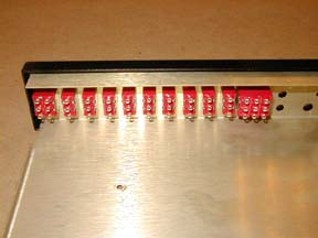
After the hook
up wires are run from the sides and back of the Board it is time to wire
the switches. This is the second place I had the most trouble. There are
no diagrams in the assembly "manual" to indicate which terminal
is which on the switches. I examined every switch with a 10X loupe and
could not find any markings on them either. I used a multi meter to find
out the correct terminals for the nine SPDT switches. So I assembled everything
except for the S-1 and S-11 switches.
|
|
|
|
|
|
|
After an Email to Jim asking
for some clarification, he told me to look in the other "book"
where I found the diagram.
Why it is not included in the assembly manual (where you need it) is beyond
my logical thinking. Upon
stripping about 1/4" of insulation from the hook up wires, lightly
tin the ends with solder. Make a small hook in the soldered wire end and
insert through the correct terminal. Some terminals have up to three wires
so put them all in before soldering the terminal.
|
|
|
|
|
|
A few hours of
this and all the hook up wires will be done. You may close up the chassis
now but you will need open it back up later to calibrate the unit.
Install the Molex
type crimp pins on to the wires coming out of the three grommets. Take
particular caution in putting the right pins, male or female on to the
right wires. Then into the right Plug or receptacle.
|
|
|
|
|
|
|
| |
|
|
|
|
|

